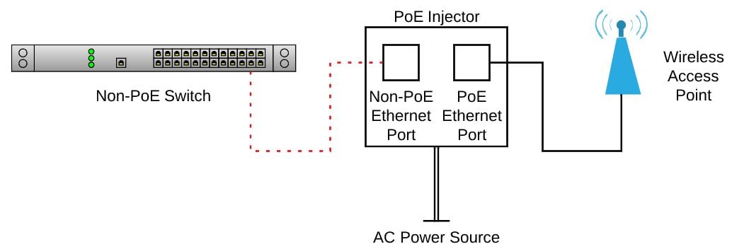
Power-over-Ethernet (PoE) sends DC power and network data through the same Ethernet cable. A PoE link has two sides: power sourcing equipment (PSE), such as a PoE switch or Ethernet injector, and a powered device (PD), which receives that power. This board is my PD-side dev board for learning wired networking, high-speed PCB layout, PoE front-end design, and register-level Ethernet firmware. This revision focuses on receiving PoE power and bringing up the W5500; a future revision will use a switching power stage.
3D Board Model
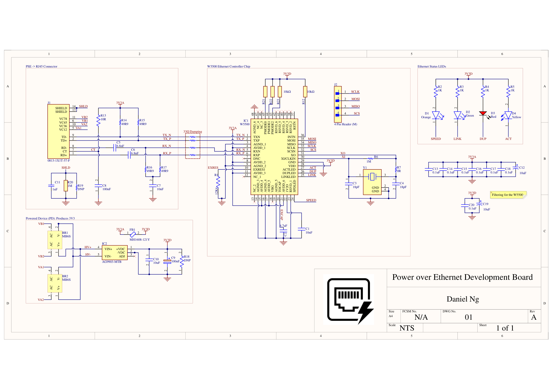
Current Schematic
System Architecture
| Subsystem | Implementation |
|---|---|
| PoE input | PoE-compatible RJ45 MagJack routes Ethernet data to the W5500 and PoE voltage nodes to bridge rectifiers. |
| Power conversion | Bridge-rectified PoE input feeds an isolated Silvertel PoE PD module to generate the board supply rail. |
| Ethernet controller | W5500 provides the hardwired TCP/IP Ethernet interface and communicates with the ESP32 over SPI. |
| Digital control | ESP32 controls chip select, reset, interrupt handling, and packet-level application firmware. |
| Debug access | Breakout/test access is planned for SPI, reset, interrupt, 3.3 V, ground, and PoE power rails. |
Firmware Bring-Up Plan
SPI Driver Bring-Up
- Initialize ESP32 SPI pins for SCLK, MOSI, MISO, and active-low chip select.
- Read the W5500 version register to confirm basic bus communication.
- Control W5500 reset timing from firmware while preserving a manual reset path.
Network Validation
- Monitor link, speed, and activity status during cable insertion and router connection.
- Bring up static IP or DHCP network configuration.
- Expose a simple UDP/HTTP diagnostics page for board status and link testing.
Hardware Bring-Up Plan
- Verify PoE input polarity after bridge rectification before connecting downstream circuitry.
- Measure the generated board rail under no-load and ESP32/W5500 load conditions.
- Confirm W5500 VDD/AVDD rails, reset state, crystal startup, and SPI signal integrity.
- Connect to a router or switch and validate link LEDs before running UDP/HTTP firmware tests.
- Use test pads and debug headers to isolate power, reset, SPI, and Ethernet link faults during first revision bring-up.
Design References
WIZnet W5500 Reference Schematic
Official W5500 Ethernet reference schematic and RJ45/MagJack guidance.
W5500 MagJack Schematic Image
WIZnet schematic export for a W5500 design using an RJ45 connector with magnetics.
Silvertel Ag9900M PoE Module Datasheet
Isolated IEEE 802.3af PoE module datasheet used for the PD power stage.